|
|
|
|
|
|

|
Latest News |
|
| |
|
|
| ► |
It's easy to improve both your company's as well as Scia's website visibility by putting links to each other's. We invite all our customers and partners to use this exchange form to make this trade possible. |
|
| |
|
|
| ► |
New items have been added to Nemetschek Scia FAQ section.
Here you can find the answers on frequently asked questions related to Scia Engineer, Allplan ... |
|
| |
|
|
| ► |
We are looking for engineers with a background in construction and structural engineering wishing to pursue a career as support or sales engineers based in the UAE and other locations throughout Asia. Please contact Mr. Charles Wilby for more details. |
|
| |
|
|
|
|
|
| |
|
|
|
Events |
|
| |
|
|
| ► |
Scia organizes a free 'initiation day' Scia Engineer on 30th October 2008 in Wavre (B).
Note it down! |
|
| |
|
|
|
|
|
| |
|
|
|
Software update |
|
| |
|
|
| ► |
Customers can download
the following service packs in our secured download
section. |
|
| |
- Scia Engineer 2008.0.111
(Scia Engineer 2008.1 will be available early this month)
- ESA-Prima Win 3.100.230
- Allplan 2008.0c1
|
|
| |
|
|
|
|
|
| |
|
|
|
Software
Gallery |
|
| |
|
|
| ► |
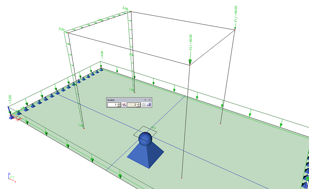
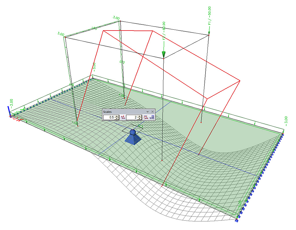
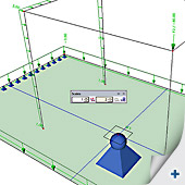
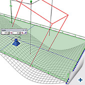
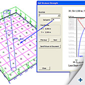
Some screenshots of the improved scale and soil interaction features available in
Scia Engineer 2008.1 (this new release will be available early this month). |
|
| |
|
|
| |
 |
|
| |
|
|
| |
 |
|
| |
|
|
| |
 |
|
| |
|
|
|
|
|
| |
|
|
|
|
|
October 2008
|
|
|
|
Dear eNews reader,
Did you know that Nemetschek Scia is the first and only 'CAE sofware'-developer with an IFC 2x3 certificate?
In this October edition of the eNews you find more information on this topic. Further we share some Allplan news, more specifically about the Allplan Freeform Modeller. We also like to inform you about the 'COINS' initiative and, as usual, our Customer Services Department gives you some useful tips!
And do not forget: "Never give up! By hard work the future is yours …", one of the favourite one-liners of Scia’s CEO, Jean-Pierre Rammant.
|
|
|
|
IFC certification for Scia - What does this bring to the construction community? |
|
|
|
| |
|
 Scia is the first and only CAE software supplier with an IFC 2x3 certification on its structural model. IFC (Industry Foundation Classes) is gaining importance as the international standard for exchanging data in the construction industry, see www.buildingsmart.com. Scia is the first and only CAE software supplier with an IFC 2x3 certification on its structural model. IFC (Industry Foundation Classes) is gaining importance as the international standard for exchanging data in the construction industry, see www.buildingsmart.com.
Rather than explaining the technology of IFC, we focus on the practical use. Through IFC (import and export) structural engineers can exchange the structural model with architects (using software that is IFC compliant, which practically all 3D packages have).
There is more, the neutral file with the project data information opens a world of new applications:
- With the free viewers available on the web anybody can visualize the 3D structural model (project owner, contractor, suppliers, …); there is also software to check the structural model for clashes between members (or additional objects like HVAC)
- IFC models are used by contractors for:
- Construction planning & scheduling
- Quantity take-off and cost estimation
- Other design colleagues use the IFC model as a basis for environmental analysis (sunlight, energy analysis), lighting simulation, acoustics
- Governmental bodies are requesting an IFC model for the submission of construction documents (e.g. Norway, Singapore, General Services Administration/USA)
In Scia Engineer a BIM and workgroup toolbox gives additional functions for structural modelling and IFC.
For the readers interested in IFC capabilities, we refer to the recent publication “BIM Handbook, a guide to Building Information Modelling” by C. Eastman, P. Teicholz, R. Sacks,
K. Liston, Editor J. Wiley, 2008.
On the right, you can see an IFC project from an external source, read into Scia Engineer, visualized by a free IFV viewer in 2 view options. (image 1 and image 2).
We invite you to download and use the FREE Nemetschek IFC viewer. |
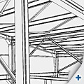
image 1 |
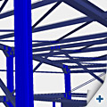
image 2 |
|
|
 |
|
| |
Product News: 3D Modelling with Allplan Freeform Modeller |
|
|
|
| |
|
|
| |
|
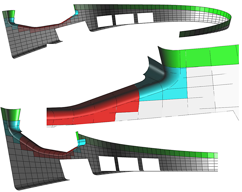
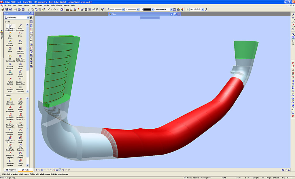
Contemporary building projects never cease to become more and more eye-catching. After all, a conspicuous design brings along quite some advantages. The concerning architect is able to build up a name and consequently gather extra orders. Also from the technical point of view new challenges have to be taken up. An organic architectural design enforces engineers to search for other and/or new building techniques. In a 3D CAD-world the shape is everything. Views and sections are derived from the form; the stability study and/or design of reinforcement is/are becoming a lot more unambiguous and correct. Detection and reduction of mistakes in the design phase usually results in a lower cost price and this is favourable for every party involved. More complex forms require however adapted 3D modelling techniques.
In Allplan there is a module for 3D Modelling, by which it is possible to model most volumes. Besides this, Allplan includes a series of architectural objects that can be considered as intelligent 3D modelling tools. These are provided with specific parameters; after modification of which the model will change accordingly. A third possibility to create free forms is the FreeForm-modeller, based on our Scia Engineer platform.
An example:
The architect is coming up with a design of a concrete façade with the following free form: (image 1)
Here we are dealing with double curve surfaces. Theoretically this can be done with the module 3D modelling but actually it is too complex for this program. In the architecture programs there is no real solution to be found either.
FreeForm modeller however has all the necessary tools to create the model.
A short description of the procedure:
- Start the FreeForm modeller from the module Concrete design => tab Freeform Modeller
=> function start 'SCIA.ESA modeller'
- In this modeller we read in our data (DWG). The object to be modelled is divided into portions. Each portion is delimitated by 2 limit Lines from the imported DWG.
- Model a “General fixed solid” per portion. This function is situated under Construction
=> Model/Draw
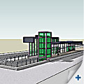
- When all pieces are created as a General fixed solid, a form recognizer is applied. This Application will translate the General fixed solids into an intelligent object (wall, floor, beam, column, …)
(image 2)
- The last step is saving the file and closing the FreeForm-modeller. The design is transferred to Allplan; here it is also recognized as a volume. This is considered as a starting point for further operations (3D modeller), making sections, views and designing reinforcement. (image 3)
|
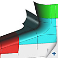
image 1
|
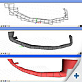
image 2
|
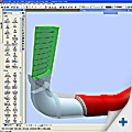
image 3 |
|
|
| |
|
|
| |
Market News: COINS, "Building sector chooses for life cycle integration" |
|
|
|
| |
|
|
| |
 
Having access to adequate information at any moment, better traceability of decision-making processes and lower building costs: these are the goals the building sector wants to achieve with an ultimate approach, in which in each phase of the construction of a building is coupled to a 'construction information model'.
A very promising initiative regarding this topic is COINS; this acronym stands for Constructive Objects and
INtegration of processes and Systems. This initiative for improving the progress of building processes is largely based by a huge part of the Dutch building community. The aim is to be able to improve the building processes by the intelligent use of 3D objects. In order to achieve this goal, COINS is developing engagement systems regarding 3D building objects and their matching management information as well as engagement systems concerning procedures.
One of the characteristics of the building sector is that there are always a lot of parties involved in the construction of a building and that there is hardly ever a party that manages the life cycle as a whole. This is an important difference with regard to other sectors like e.g. the aircraft and shipbuilding industry, where life cycle management has already become widely accepted and where spectacular improvements have been realized. The number of mistakes has been reduced, flexibility has increased and the competitive position has been enhanced in these sectors. Based on this experience, COINS has already translated those procedures into corresponding procedures in the building sector. Where possible, existing international standards and methods were used. Currently the practicability of the proposed methods is being tested by a lot of the participating partners.
 A few projects have already been dealt with; e.g. a project of Movares and ProRail on the integration of the functional specification and design of the new railway station Utrecht Lunetten and a project of BAM on the determination of quantities. These projects are now transferred to the next involved parties, who learn on their part from the previous experiences. Based on all these experiences, frames of reference are developed preparing the road for a more transparent and more efficient building process. A few projects have already been dealt with; e.g. a project of Movares and ProRail on the integration of the functional specification and design of the new railway station Utrecht Lunetten and a project of BAM on the determination of quantities. These projects are now transferred to the next involved parties, who learn on their part from the previous experiences. Based on all these experiences, frames of reference are developed preparing the road for a more transparent and more efficient building process.
More information: www.coinsweb.nl.
|
|
| |
|
|
| |
Customer Project: Renovation project of Boulogne Billancourt by Profil du Futur (F) |
|
|
|
| |
|
|
| |
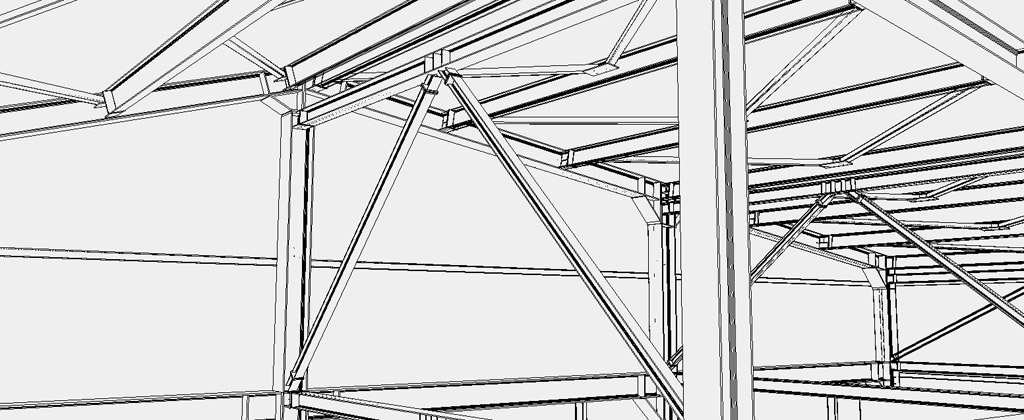
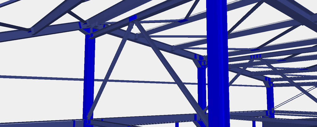
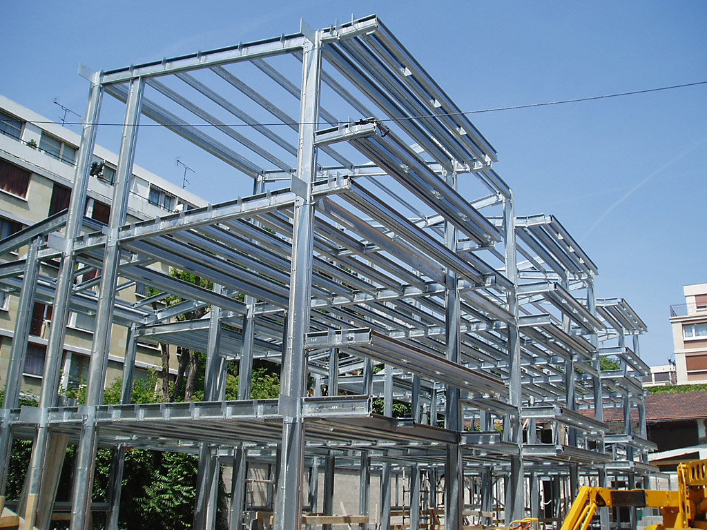
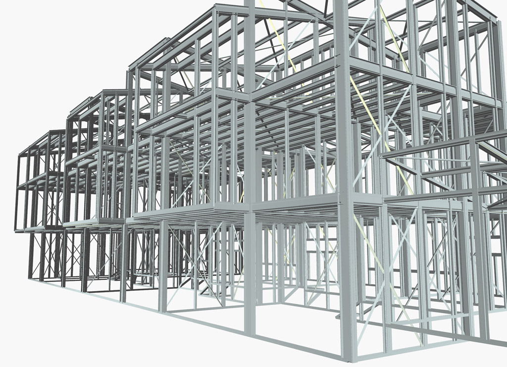
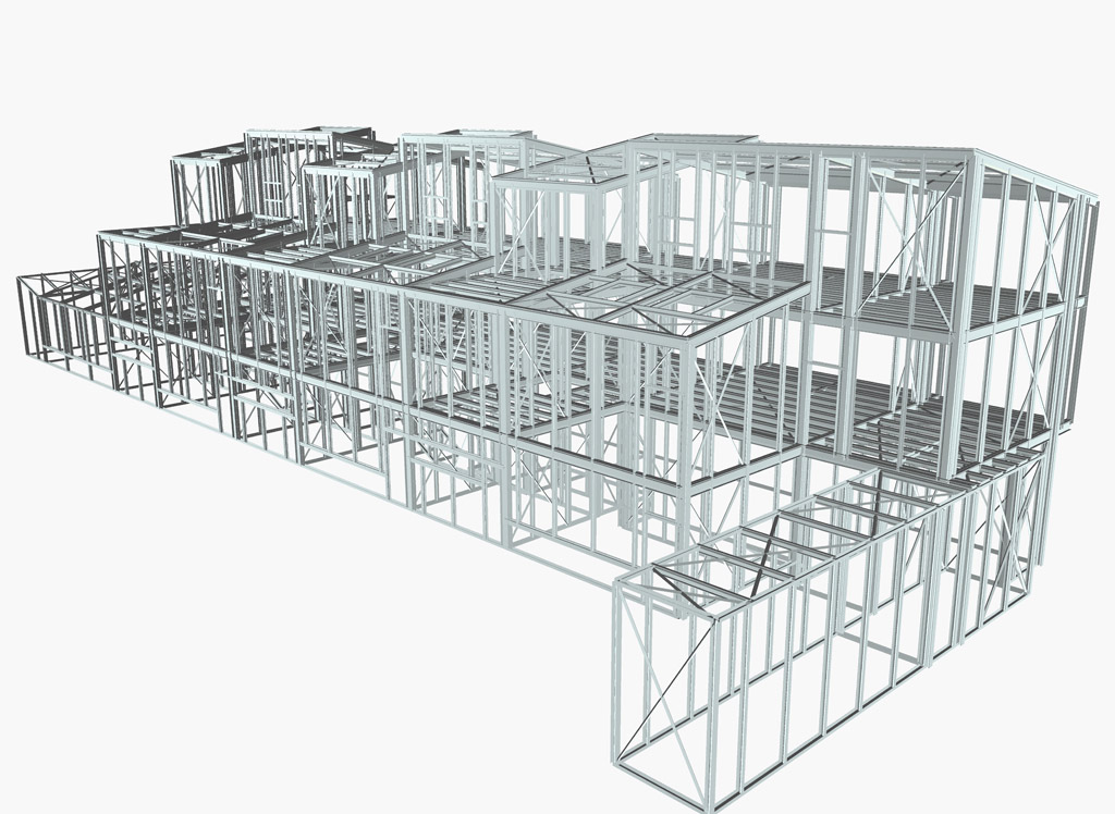
 Profil du Futur, one of the main French manufacturers of steel structures, profits from its membership of Arcelor Construction, subsidiary of ArcelorMittal, to conceive and realise highly technical constructions. Profil du Futur, one of the main French manufacturers of steel structures, profits from its membership of Arcelor Construction, subsidiary of ArcelorMittal, to conceive and realise highly technical constructions.
 With over 30 years of experience in more than 20 countries, Profil du Future proposes steel solutions which are adapted to the needs of each user and to the specificity of each building, whether industrial or residential. With over 30 years of experience in more than 20 countries, Profil du Future proposes steel solutions which are adapted to the needs of each user and to the specificity of each building, whether industrial or residential.
The use of thin galvanized sections and their assembly by robots (with screws and/or bolts) gives free play to architectural creativity while allowing the realisation of any volumes, any forms, and guaranteeing a complete assembly in the factory itself.
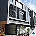
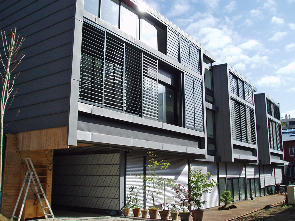
Renovation project of Boulogne Billancourt (F)
It regards the creation of a collective of 3 residences under one roof, for the account of Loftissime Immobilier.
The dimensions are: length: 39,00 m. width: 5,30 m. height: 9,80 m.
The site is located at the doors of Paris in a backyard; the building is conceived in a congenial way with an optimized use of steel in the structure.
The challenge was to create useful volumes and spaces while combining high-tech materials. Passages for wiring, providing space under the ceiling, facilities for roll-down shutters … are all incorporated in an intelligent and natural way in the structure.
The low total weight of the steel framework has led to substantial savings in the budget of the micro piles. The profitable interface between skill and the engineering office has contributed in a very significant way to the saving of time with regard to the realization of this project.
On completion, the owner was very pleased that the building offered the entire thermal, acoustic and safety comfort that he had wished for his clients. |
|
| |
|
|
| |
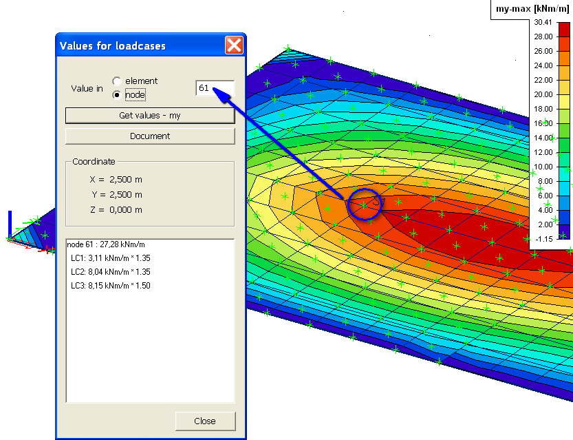
Tips & Tricks: Detailed results in mesh node in Scia Engineer |
|
|
|
| |
|
|
| |
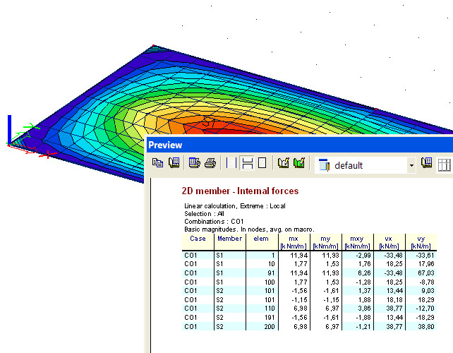
 An improvement has been made for the output of results in 2D elements in Scia Engineer 2008.1. An improvement has been made for the output of results in 2D elements in Scia Engineer 2008.1.
It has always been possible to view the results in the form of isobands, numbers, labeled isolines and so on.
Furthermore a preview in which the output values were given for the desired results has also been available . It shows a global overview of the average values and extremes of the output parameter.
In this case however, the user has to know the exact location of the mesh element. (image 1)
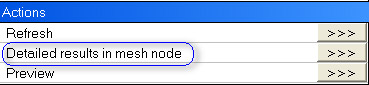
From version 2008.1 on, a new functionality has been implemented to facilitate the check of results.
For example, consider the internal forces in a 2D plate. Under the button 'Actions', a new option is available: (image 2)
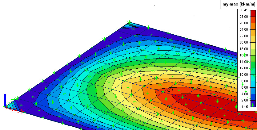
If the user clicks the button 'Detailed results' in mesh mode, Scia Engineer asks to select the member in which the vertexes will be displayed: (image 3)
|
|
|
|
image 1 |
image 2 |
image 3 |
image 4 |
In each finite element node (FEN) of the mesh or on the centroid finite element node (CFEN) a vertex appears.
When selected, the chosen vertex shows the detailed results. (image 4)
The number of the mesh element together with the detailed information of the combination and the corresponding result is given.
|
|
| |
|
|
| |
About
this Nemetschek Scia eNews |
|
|
|
| |
|
|
| |
- We would like to encourage you to give us your current e-mail
address, if the one we used for this message, would not be correct
or if you want us to send it to another address.
- If you would like to unsubscribe from this eNews, just send us an e-mail with 'unsubscribe' as
the subject followed by the e-mail address to be deleted.
- Please let us know if there are any topics in which you are interested.
We would also like to hear any suggestions or ideas you may have
on improving this eNews. You can respond here ...
|
|
| |
|
|
| |
|
|
|
|
|
|
|
|
| |
|
|
|
Nemetschek
Scia ● Copyright
© 2008 ● [email protected]
|
|

 With over 30 years of experience in more than 20 countries, Profil du Future proposes steel solutions which are adapted to the needs of each user and to the specificity of each building, whether industrial or residential.