| |
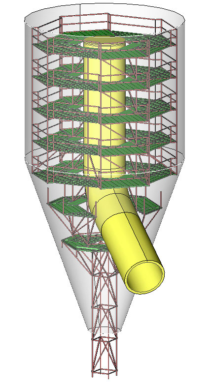
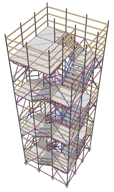
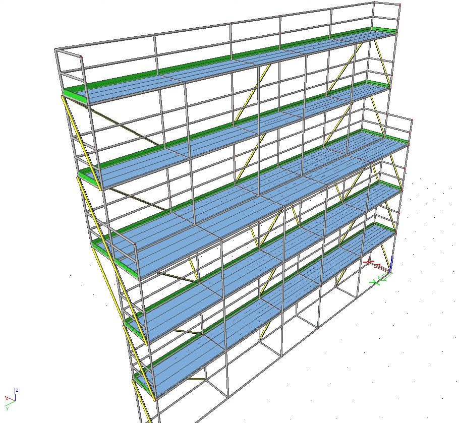
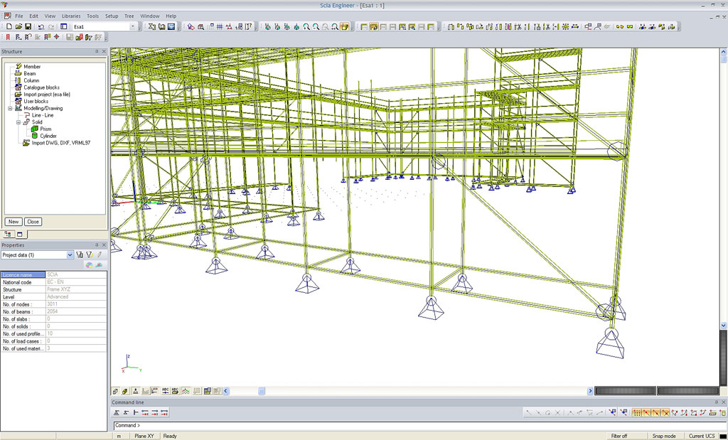
A major shift is ongoing in the construction industry towards maintenance of existing infrastructure and industrial equipment. Be it civil structures (bridges, tunnels, towers), plant equipment (tanks e.g.), ships, aircrafts or buildings, renovation and reparation work is a must. In many cases the contractor needs access to structural parts, usually not within easy reach, and uses therefore scaffolds. In principle there are two main types: ‘tube-and-fit’ and ‘system’ scaffolds. Scia gives an answer to the following questions: what are the required materials to set up a full scaffolding, how does it look visually (and in drawings) and what is the structural safety, taking into account the latest building codes? Indeed, scaffolding structures are quite flexible and unstable; too many deadly accidents have been reported due to complex and often unsafe assemblies.
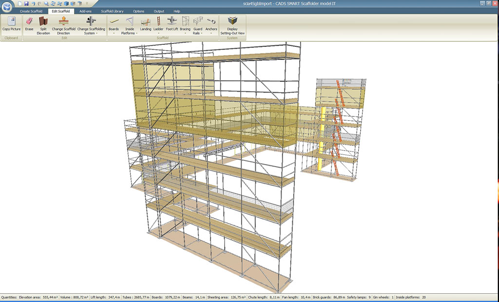
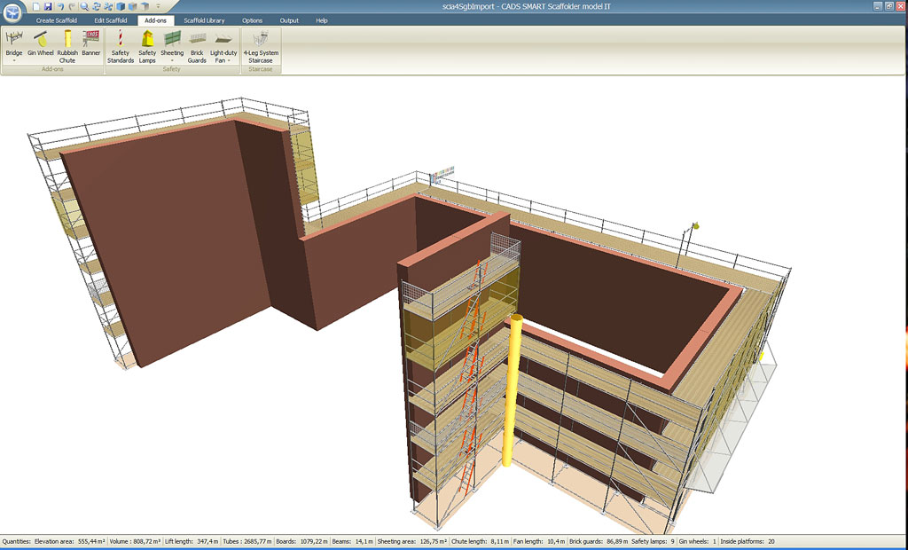
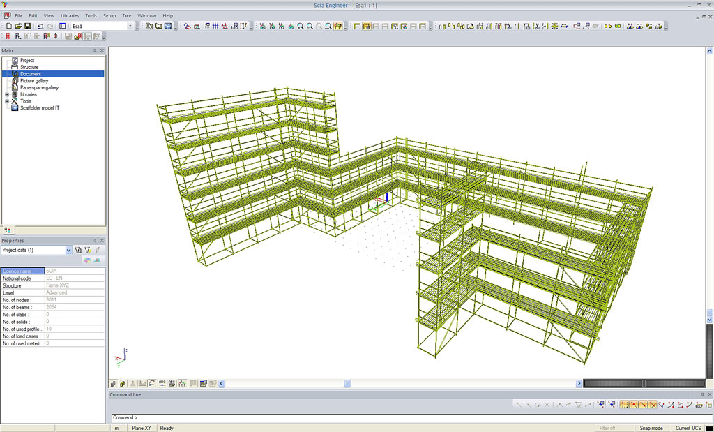
Scia is helping the industry to improve safety and precision. At first a very straightforward modeller for scaffolds has been worked out, together with our development partner CADS UK. The modeller is ready to be used by non-technical staff, i.e. contractors, builders, planners…, and generates quickly a scaffolding structure, a free-standing one or built around an existing structure. The required material list and drawings are generated from the 3D model. And for more complex scaffolds a dedicated Scia Engineer package is worked out.
This is able to calculate precisely the deformations, the internal forces and stresses and the safety of all members under a variety of loadings and support conditions. The technical complex behaviour of fittings is closely simulated and the latest design codes are incorporated as well. It is evident that the modeller is linked with Scia Engineer, covering the whole spectrum from simple to complicated scaffolding structures.
Designers, contractors, scaffold suppliers and scaffold producers are offered an economical yet technological advanced design tool. |
|
|
| |
 About the KAEFER group About the KAEFER group
The KAEFER group is established worldwide in more than 40 countries with a workforce of over 15,000 employees. They are active in the following sectors: heat- and cold insulation, scaffolding, noise reduction and fire protection, offshore, shipbuilding and construction. KAEFER N.V. Belgium and KAEFER B.V. Netherlands are mainly active in the field of scaffolding, insulation, heating pipes and asbestos removal, both in the construction sector and the industry.
About the project
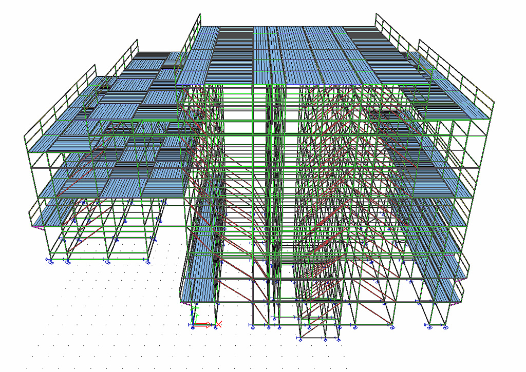
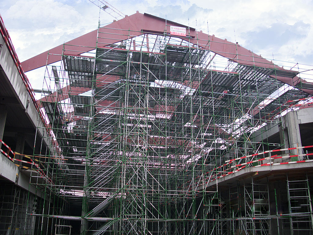
At the end of 2008, KAEFER Belgium received a contract to build a complex assembly of scaffolds in the atrium of the mall ‘Sint-Janspoort’ in Kortrijk (B) from its client THV Wijngaard, a temporary business association between the companies Van Roey NV and Van Laere NV. Besides the hiring out, the assembly and disassembly of the scaffolds, the assignment consisted in the design of:
- a gigantic floored scaffold for works on the enormous glass dome, this combined with lateral scaffolds, each of 2m of height, for the masonry work at the sidewalls;
- the support structures for the heavy steel frames of the glass dome.
The engineering department chose the Scia Engineer software for this project, e.g. for the determination of the reaction forces acting at the bottom of the spindles. Also a few constraints had to be taken into account.
On the one hand, the ground surface (a concrete slab), acting as the base level for the scaffold, could only carry a limited load (a maximum concentrated load of 4 tons) and on the other hand the client insisted on placing the least possible supporting points. An initial investigation already pointed out that the combination of the two constraints was not easily feasible. Only after an intensive period of ‘trial and error’, KAEFER was able to design the ideal structure for the client. In order to come to an optimal spreading over the ground surface of the most heavily loaded points of support, KAEFER chose for a special scaffolding technique which conducted the forces to the underlying concrete slab.
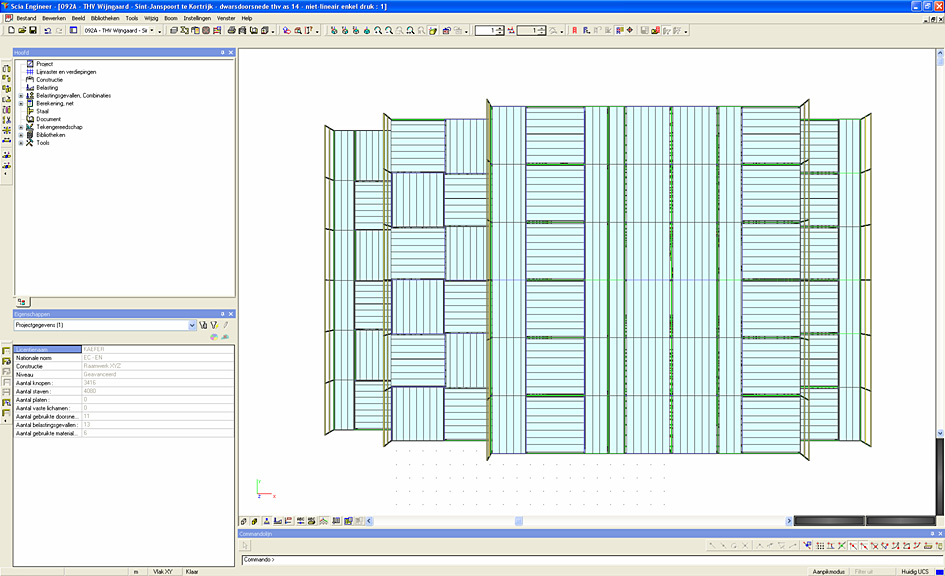
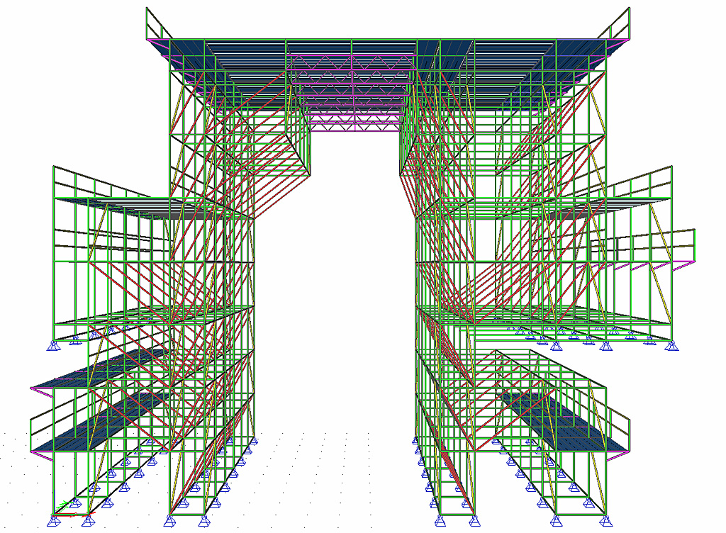
The dimensions of this scaffolding: length: 112m, width: 27.5 m, height: 17m; floor surface of the scaffold: 5.000m ². The 27 support towers with a height of 23m for supporting the huge steel trusses were built in combination with the scaffold, they were however independently charged. The applied vertical force per point of support of these frames was 19 tons. Given the limited size of the support towers (1.57m x 1.57m), special scaffolding constructions were developed to achieve this.
Some figures about this project:
54.000m ³ of scaffolding; 450,000 kg of material = 450 tonnes; 88,000 running meter of tubes/floorboards = 88km. |
|
| |
 When doing the calculation and design of a scaffolding, Scia Engineer is the perfect tool. The programme allows performing Scaffolding checks on the beams and executing checks of the couplers. For those options you need the module esasd.13.01 and you have to activate the Scaffolding functionality. When doing the calculation and design of a scaffolding, Scia Engineer is the perfect tool. The programme allows performing Scaffolding checks on the beams and executing checks of the couplers. For those options you need the module esasd.13.01 and you have to activate the Scaffolding functionality.
The Scaffolding Check is executed according to the Eurocode EN 12811 and can be accessed from the menu Steel under Check, next to the Section check and the Stability check.
The Coupler Check is discussed below.
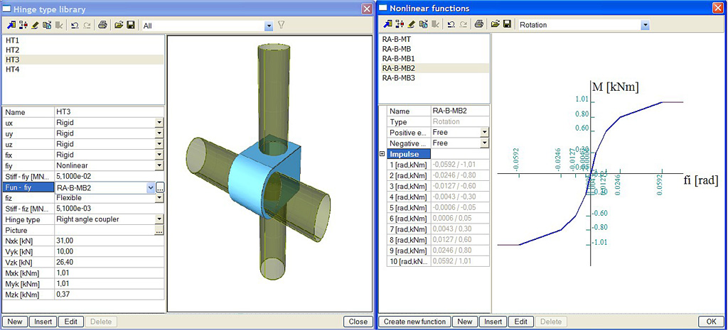
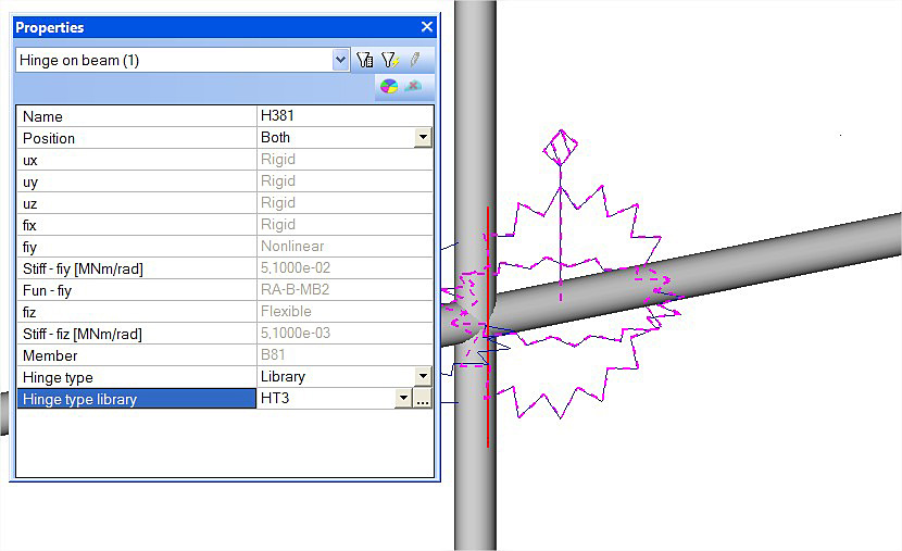
First, input the properties of your coupler by navigating to “Libraries -> Structure, Analysis -> Hinge type” (see Figure 1)
In this menu you can insert a coupler – you have the possibility to input the real stiffness for each translation and rotation component and the maximum allowable forces according to the values given by your supplier.
In Scia Engineer some default property values are already inputted for base jacks, right angle couplers, friction sleeves, swivel coupler, etc.
After inputting the correct stiffnesses you can place the couplers to the ledgers and guardrails on the construction by adding hinges on the beam ends and changing the Hinge type to Library in the Properties window.
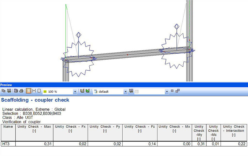
It is necessary to perform a calculation before the coupler check is available. In this calculation (see Figure 2) the inputted stiffnesses are taken into account.
In the Steel menu a check for the couplers can be performed by choosing Scaffolding – Coupler Check.
In this check (see Figure 3) the internal forces on the beams will be compared to the maximum allowable forces resulting in a unity check. This check will inform you if the coupler is sufficient or not. |
|