| |
The Nemetschek Engineering User Contest is an international competition for users of software, developed and distributed by the following members: Nemetschek Scia, Nemetschek Allplan, Nemetschek Engineering (Precast), Frilo and Glaser.
In the last 2009 edition 120 projects from 14 countries were elaborated with great detail. If you have not yet received the Nemetschek Engineering User Contest Book 2009, we will gladly send you a copy, completely free of charge. You can request your book here or download it in PDF.
The Nemetschek Engineering edition 2011 will continue the success of the previous editions; through a large distribution of the Nemetschek Engineering User Contest Book the quality of your engineering services will be noticed by many potential clients. Many magazines and newsletters from the Nemetschek Engineering companies will bring the participating projects in the international spotlights.
Why should you - as one of our users - participate in this contest?
- Several thousand copies of the User contest book will be distributed in the engineering community.
- Your projects will be studied by an international jury, giving feedback on the level of engineering quality and creativity.
- There are five categories (Buildings, Civil Structures, Industrial Plants, Industrialized Planning, Special Projects)
in which you can win 1 500 € each.
- The nominated and winning projects will be communicated to the international press for publication in magazines and websites.
- You will share experiences with colleagues how design and detailing tasks are performed in real situations.
- You get a quick overview on all ongoing construction projects where Nemetschek software is used for engineering purposes.
Participating is simple
This contest is meant for projects which have either been completely realized, which are still in progress or from which the design or detailing is being done, with the help of any of these Nemetschek Engineering software tools: Allplan Engineering, Allplan Precast, Frilo Statics, Glaser -isb cad-, Scia Engineer, Mseries, Scia Steel and PP Manager.
It is very easy to assemble the project presentation data, we provide guidelines and templates.
With little effort, you obtain a maximum exposure.
You find all practical information regarding the contest on www.scia-online.com/contest.
Start uploading your projects today!
Read also our Press Release (PDF).
|
|


For more information and subscriptions click here...

|
|
| |
 About the engineering office About the engineering office
The IGUBA company was established in 1997. The owner, Ivan Guba, is a static engineer who works on his own. He is active in structural engineering, civil engineering (static and construction), design of the static of residences and commercial buildings, diagnostics of bearing constructions and technical consulting.
About the project
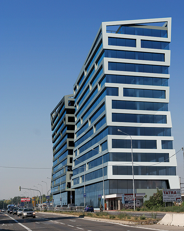
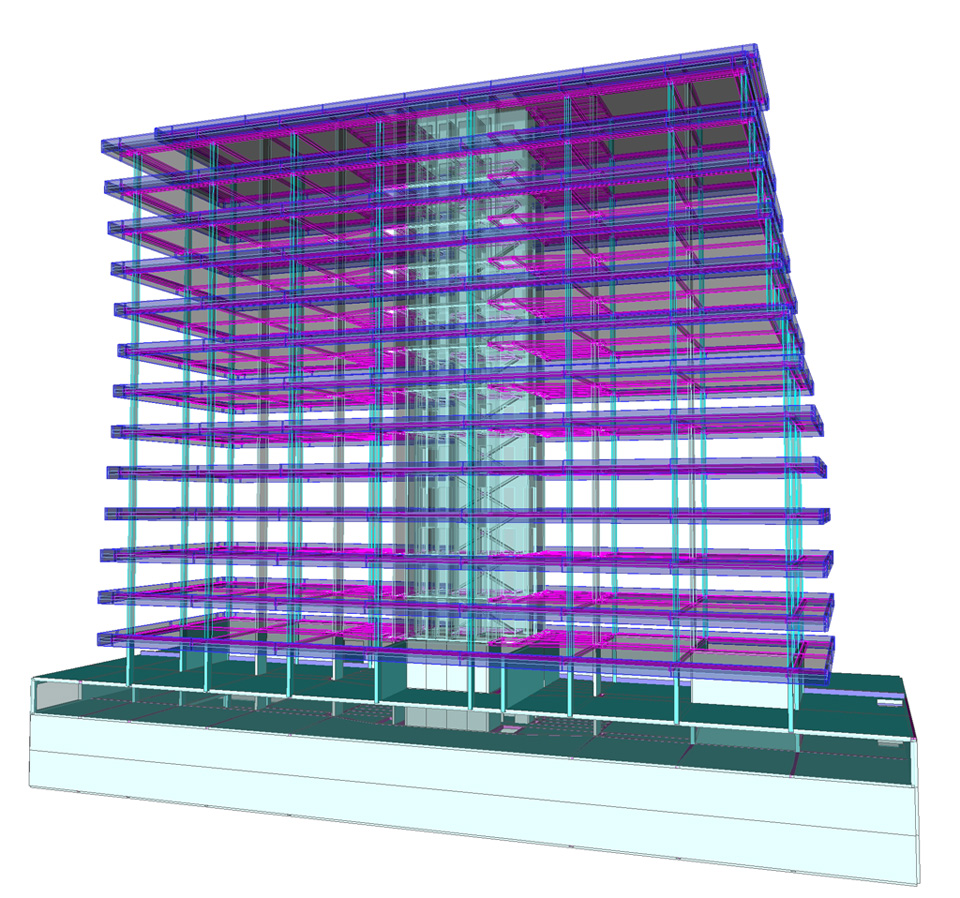
This project regards the static of the reinforced concrete structure (C30/37) for the Emporia Towers Building in Bratislava–Slovakia. The total length of these two towers together is 2 x 53,1 = 106,2m. The reinforced concrete structure of the Emporia Towers has 21 modules, consisting of a box girder type 13-storeyed tower having a breadth distance of 17,40m, and between which there is an expansion gap of min. 30mm.
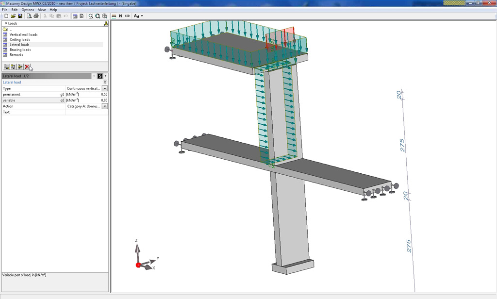
The supporting structure of the building is made of reinforced concrete consisting of vertical wall and horizontal board elements forming a compact unit with transversal, as well longitudinal stiffening in horizontal and vertical planes. On the supporting circumferential walls there are, fastened from the outside, warming panels of a planar weight of 30kg/m², protecting the hall from meteorological and precipitation influences. A thermal barrier is also included. The horizontal structures of the ceilings are formed with monolithic plates of a thickness of 250mm with a span of max. 7,30m. The double-armed stairway is monolithic too. The individual towers are stiffened by monolithic circumferential walls and an internal stairway-holding wall. On the front wall we see the main entrance with a dominant oblique monolithic roof.
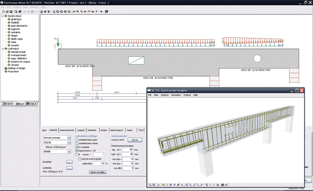
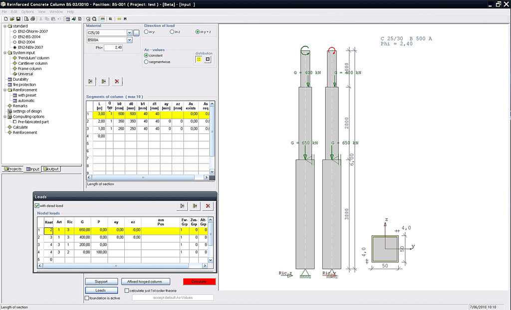
The foundation and the bearing structures were designed according to ENV 1993-1-1:1992 Eurocode 3. The design consists of the calculation and evaluation of a number of load cases and their complex combination effect. Besides the dead load (own weight) was considered the live load; for ceilings it was the standardized value 2,50kN/m², for the stairway 3,00kN/m², for snow loading (area II.) so = 0,70 kN/m2 and for wind loading wo = 0,55 kN/m² (during the erection and on the final building). After that was considered seismicity 7o MSK-64, category "A" and temperature loading (the shell structure received higher temperatures than the column support during the operation).
The static calculation was done with Scia Engineer (NEXIS). The 80 most precarious combinations were calculated according to ENV 1993-1-1:1992 Eurocode 3 with coefficient 1,35 in two basic combinations (bearing capacity and deformations).
The model contains 1385 macros in 1D and 2D. |
| |
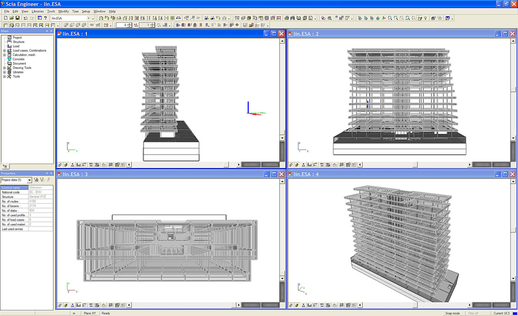
 A new option in Scia Engineer 2010.0 is the 'tracking' mode. This will be helpful in the modelling process of a new project.
Tracking can be activated via a button at the bottom right corner of the Command line. A new option in Scia Engineer 2010.0 is the 'tracking' mode. This will be helpful in the modelling process of a new project.
Tracking can be activated via a button at the bottom right corner of the Command line.
Two new definitions have to be pointed out:
1) A tracking point is a point from which rays are displayed and distances can be entered. An existing node can be assigned as tracking point by pressing [Shift] and moving the cursor over the node. The tracking point is indicated by a blue rectangle (see image 1). The distance of the cursor along the ray is displayed in a tool tip. For rays following the X, Y and Z directions of the current co-ordinate system (GCS or UCS), the default colours (red, green and blue) are used.
When entering the first node of a new member, rays are displayed from this point. Next, an existing node can be assigned as tracking point, and then it's possible to snap to the intersection point of two rays (see image 2).
|
|
|
|
| Image 1 |
Image 2 |
Image 3 |
Image 4 |
2) A tracking curve is an edge of a 2D member which can be used to snap to. The edge of an existing plate or wall can be assigned as tracking curve by pressing [Ctrl] and moving the cursor over the edge. The tracking curve is indicated by a blue line (see image 3).
Now it is possible to snap to the intersection point of the tracking curve and a ray.
The Setup for tracking can be found in the 'Dot grid and tracking setting' item on the Tools toolbar (see image 4).
By default tracking rays are displayed in the X, Y and Z directions of the current co-ordinate system. Other directions can be added by entering values in the Angles [deg] box.
Attention: During the modelling process, these angles are always measured in the active working plane. |