|
|
|
|
|
|
|
|
|
|
New Software Updates |
|
| |
|
|
| ► |
Customers can download
the latest service packs from our secured download
section.
|
|
| |
|
|
| |
- Scia Engineer 2010.0.314b
- Scia Steel 2009 SP7
- Allplan 2009-2
- Allplan Precast 2008.2a3
|
|
| |
|
|
| ► |
 Get an automatic notify through RSS when a new Scia Engineer Service Pack is available. Get an automatic notify through RSS when a new Scia Engineer Service Pack is available.
|
|
| |
|
|
|
|
|
| |
|
|
|
Software
Gallery |
|
| |
|
|
| |
Thanks to Adams Bouwadviesbureau bv |
|
| |
|
|
| |
 |
|
| |
|
|
| |
 |
|
| |
|
|
| |
 |
|
| |
|
|
|
|
|
| |
|
|
|
|
June 2010
|
|
| |
Dear reader, in this months' Enews...
|
|
|
|
| |
|
| |
Coming soon: Nemetschek Scia dedicated webshop and Scia Engineer 2010.1 |
|
|
|
|
| |
|
|
| |
First and foremost Scia wants to share its joy with regard to the big success of the new dedicated website
www.eurocodes-online.com. Only one month in the air and our current and future users of Scia CAE applications have already found their way to the technical articles, up-to-date information on Eurocodes in the different countries, examples of good practice, Q&A and much more on this special website.
Secondly, very soon Scia will be launching a new webshop. The shop will offer Nemetschek software but also other products and services such as trainings and special offers. An example: Scia will be launching via this webshop a dedicated ‘Scia Engineer - Eurocode Starter Package’ for beam type structures at a very affordable price. So, watch your email!
And last but not least: following the release 2010, an intermediate version of Scia Engineer rel. 2010.1 is being finalized: in this version National Annexes to the Eurocodes for several of the countries where Scia is active are available. The good news is that clients who have maintenance on the Eurocode design software will receive all available National Annexes for free! |

|
|
|
| |
 |
|
| |
Engineering meets Art |
|
|
|
|
| |
|
|
| |
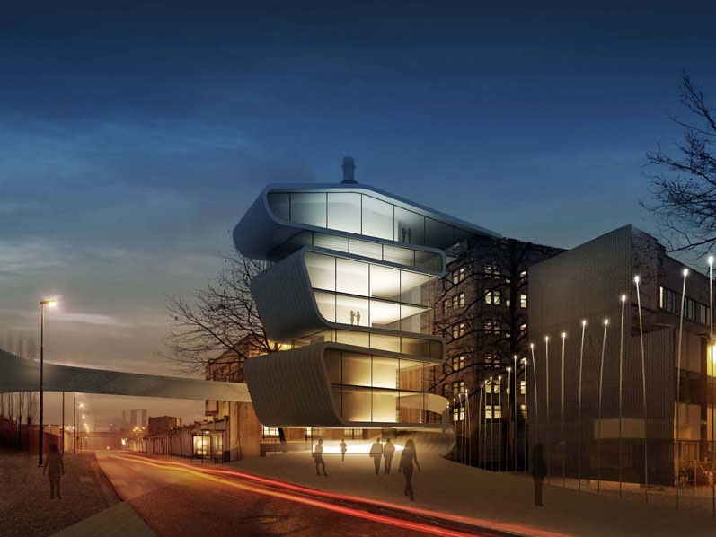
Recent exhibitions showed the works of two Scia engineering clients, Studieburo Guy Mouton and Engineering Office Laurent Ney, respectively in Ghent (Designing Together) and Brussels (Shaping Forces - Bozar till 20.6.2010).
It is remarkable that both exhibitions were set up by architectural initiatives, yet not surprising. Both structural engineers have a similar approach to design: architecture and structural design are not separate entities; through cooperation from the start superior projects are realized. Instead of accepting an underlying role to the architect, these engineers are part of the whole design process and often trigger the projects to a high standard, emphasizing the role of engineering art.
|
|
|
|
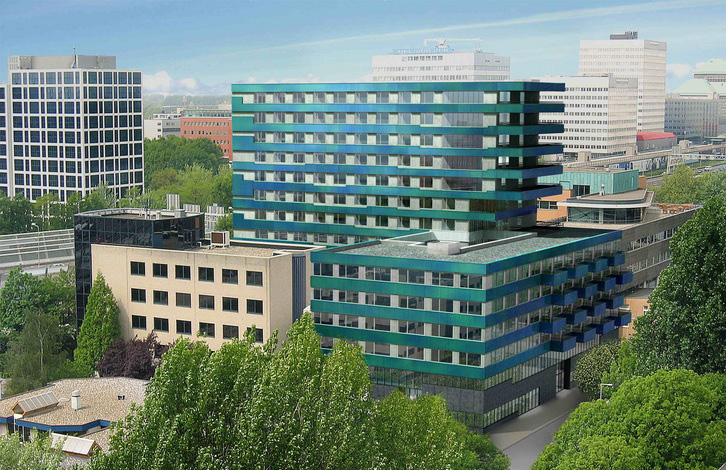
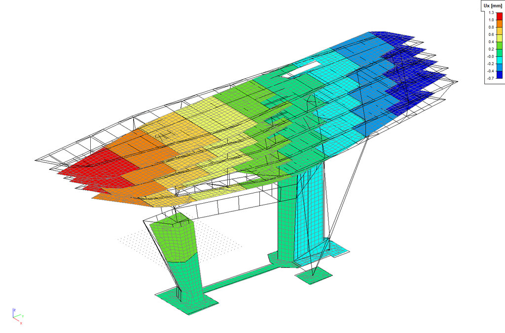
Umicore Building
Engineering Office Laurent Ney |
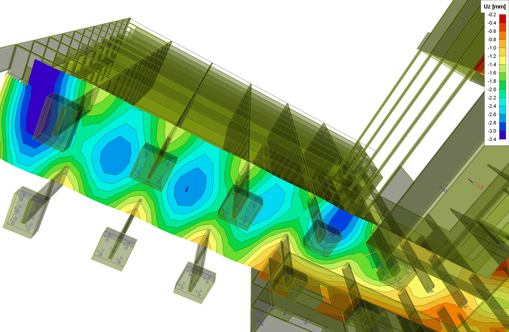
Scia Engineer - Results
Umicore Building |
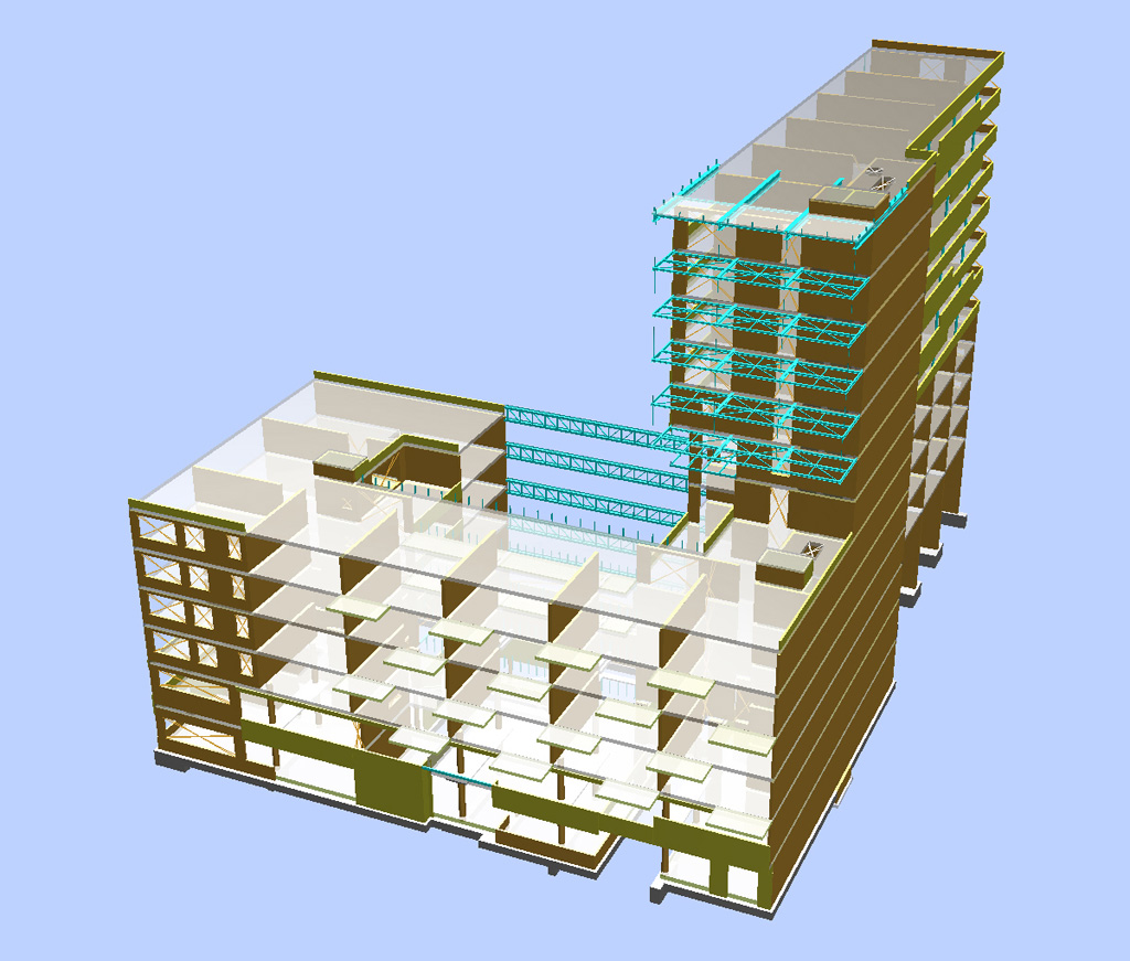
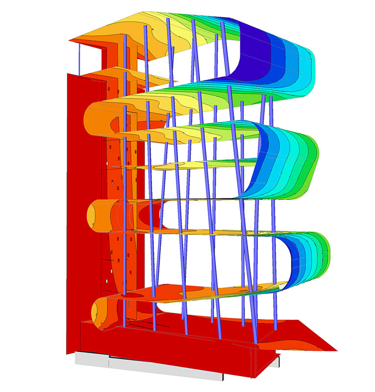
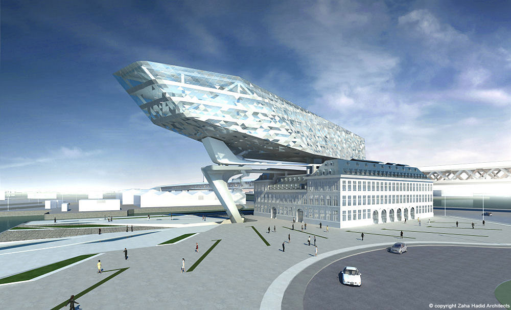
Harbour House Antwerp
(work in progress)
Studieburo Guy Mouton |
Scia Engineer - Eigenmode
Harbour House Antwerp
(work in progress) |
Needless to say that both engineering offices are amongst the pioneer users of our flagship software Scia Engineer.
Let all of us be inspired by their works. |
|
| |
|
|
| |
Seismic investigation and restoration of a Christian Orthodox Church |
|
|
|
|
| |
|
|
| |
About the project designer
Marios Filippoupolitis is a student in Civil Engineering at the University of Patras. His thesis subject, Athens Parthenon Opisthodomos architraves: Developing stresses and the effect of the connector elements, gave him the impulse to perform an in-depth study of the structural restoration analysis. Last year he benefited from the special Scia “Young Engineer” offer and since then he has been working on numerous projects using Scia Engineer, e.g. seismic investigation and restoration of old masonry structures. Other ongoing projects include the structural check and rehabilitation of an old riveted steel bridge in Sparta, Greece, a project that will be produced with the cooperation and under the guidance of the steel structures department of the University of Patras.
About the project
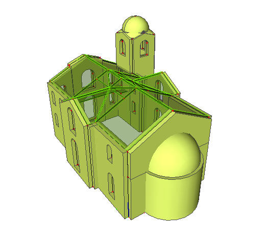
The seismic load response of a basilica masonry church with a bell tower was to be investigated. And an approach that aims at decreasing the developing stresses, by placing steel rods into the masonry’s body has been presented.
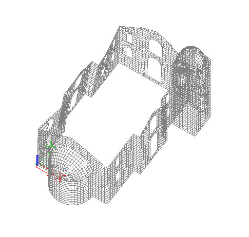
The dimensions of the church are 16,40m by 8,35m, with a height of 8m (11,35m including the bell tower). The church itself is made out of stone masonry with cement based mortar, with a thickness of 65cm, while the bell tower dome is of reinforced concrete with a thickness of 50cm.
|
|
|
|
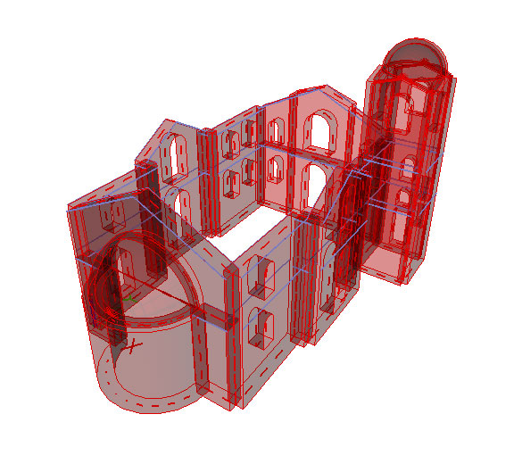
| 3D view of the model |
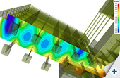
Deformed mesh of the 1st mode |
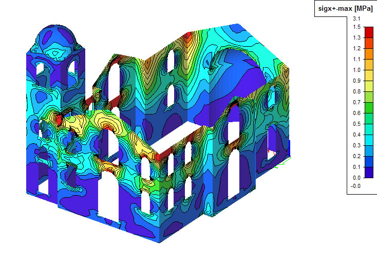
Sigma X horizontal normal stresses under seismic load |
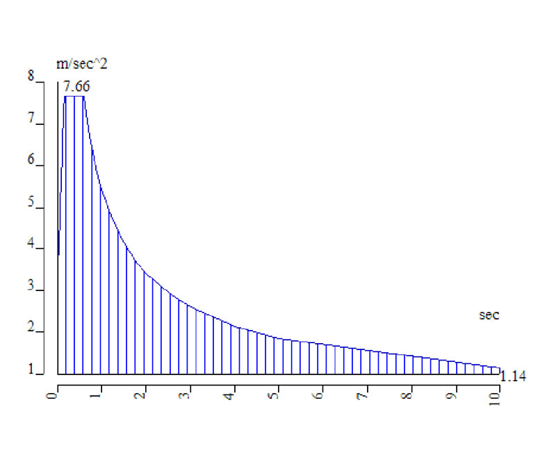
Seismic spectrum analysis |
Modelling
The first phase of the geometry simulation was conducted with Autocad. The resulting .dxf file was imported into Scia Engineer and the model was completed using Shell 2D members. The simulation of the wooden roof and the reinforced concrete slabs was conducted using 2D Panels. This approach allowed to include the weight of these structural members in the analysis, without taking into account their stiffness.
Analysis & results
The analysis was linear – elastic. The seismic spectrum analysis was performed with the design spectrum of the Greek Antiseismic Code (E. A. K. 2000). The multiple analysis results were thoroughly investigated: eigenmodes of the structure, displacements under seismic load combinations, horizontal and vertical normal stresses and principal stresses.
|
|
|
|
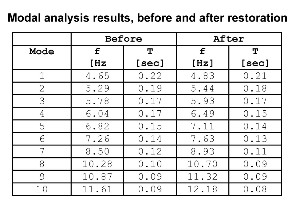
Modal analysis results,
before
and after restoration |
2 levels of steel rods in blue |
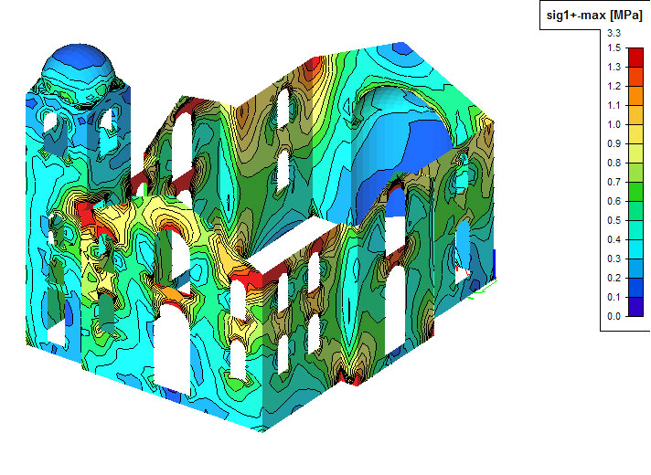
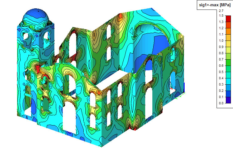
Principal stresses before… |
… and after restoration |
Restoration of the church
In order to decrease the developing stresses on the masonry walls we used the following restoration method: two rows of steel rods (Φ25) were inserted into the masonry’s body at two levels. The results of the modal analysis show that the additions of the steel rods increase the church’s stiffness. They allow decreasing both the structure’s displacement and the developing stresses on the stone masonry, the reduction of the stresses being higher at areas near the rods. |
|
| |
|
|
| |
Allplan Tips & Tricks: How to represent a section of your 3D model in the animation window? |
|
|
|
|
| |
|
|
| |
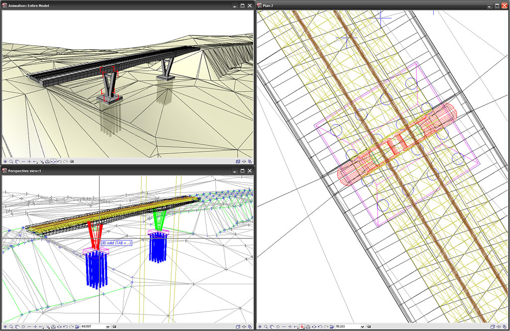
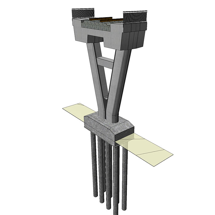
 In addition to creating visualisations, the animation window is very useful when 3D modelling. It provides a lot of insight into the 3D model and shows ‘in real-time’ the changes you make. In addition to creating visualisations, the animation window is very useful when 3D modelling. It provides a lot of insight into the 3D model and shows ‘in real-time’ the changes you make.
In the animation window, all 3D objects from the visible drawing files and layers are shown by default. When you work with large models, for example a bridge, you will get an overview on which it is probably difficult to check certain details. It is possible to turn off some drawing files/layers or use the function “animation window – selected elements” (right-click or shift-F4), to show a different selection of 3D elements. The elements however will still be shown in full.
For this example, we present a bridge model, and we would like to see the relation between all the different elements in a certain part of the 3D model. With the function “Clipping path” it is possible to display a section of the 3D model in the animation window:
- Function ‘Clipping path’ (Architecture > General)
- Set the properties, create the clipping path in plan view and enter a section identifier (use a short and easy name, e.g. “A”)
- Open an animation window, click on the ‘Activate section’ icon in the bottom-right corner of the animation window and enter the clipping path (in this case “A”)
Now you have a representation of a section in the animation window: a visualisation of all the elements within the section object. You can also create a 3D pdf from this result (right-click in the animation window > ‘Export to 3D pdf...’). |
|
| |
|
|
|
|
|
| |
|
|
| |
|
|
| |
|
|
| |
|
|
|
|
|
|
|
| |
|
|
Nemetschek
Scia - Copyright © 2010 - [email protected]
|
|